Friday 18 November 2011

Using the Morpher Modifier

To use the Morpher modifier I had to reset all of the head back to just an editable poly. This would then enable me to select objects from the scene and apply them to the head with the Morpher modifier attached.


To begin with I duplicated the head 7 times and on each head applied an editable poly modifier and renamed each head to what the facial expression would be featured in each of the heads e.g. Smiling or winking.


Head Number 1 (Smiling)

On head number 1, (renamed to smiling) I applied an editable poly and in the vertex mode moved the vertex points around the mouth so that the head would appear with a smiling facial expression.  

This can be seen in the image below:


Head Number 2 – Frowning

The same process applied as to the smiling facial expression. On this head I edited the vertex points on the eyebrows by pulling them down.

This can be seen in the image below:


Head Number 3 – Eyes Closed


Head Number 4 – Left eyebrow up


Head Number 5 – Eyebrows Up


Head Number 6 – Mouth Fully Open


Head Number 7 – Mouth Partly Open


Head Number 8 – Winking


Using the Morpher Modifier

Head Number 8 – Main Head


This head has no adjustments made to it, but it does however have the Morpher modifier applied to it.

To make the head the use facial expressions I then used the ‘pick object from scene’ tool. This allows me to assign a head to each of the slots in the Morpher channel list.


Once all of the heads had been selected I then used the auto key on the time line and at different intervals along the timeline changed adjusted the channel list facial expressions. This made a change on the main head and produced a key frame along the timeline to identify the change.


This could now be rendered into an avi file. Settings are as follows:

1080 x 720 AVI Uncompressed 800 frames – Full Timeline Scale.


Friday 21 October 2011

Final Rendered Images

Final Face Render


Left Render


Right Render


Front Render


Far Away Render


Unrendered Image


Creating the Eyes


The creation of the eyes was extremely quick and I found that the best effects gained from the eyes were to use an image sourced from the internet.

Sourced Image:
Image reference:

Sourced from:  Anime Tutorial Blogspot
Date Sourced: 16/10/2011

I began this process by creating a sphere then using the ‘move’ and ‘scale’ tool to shape the sphere into the correct size so that it could then be placed in the eye.


Now that the sphere was the correct size I duplicated it using the clone instant tool and positioned the other eye into the other eye socket. Using the instant clone option would enable me to apply the material image onto both spheres and use just one UVW modifier to position the eye image.


After Cloning:


Once I had done this I then used the material editor and applied the sourced image file on the spheres.  Using a UVW Map modifier from the modifier panel I could now use the ‘gismo’ tool so position the eye images correctly.  


Using the Hair Modifier

I choose to use the hair modifier tool as I felt that it gave my head model much more detail. To use the hair modifier I selected it from the modifier list and applied it to the head. Using the polygon mode I could now select the polygons that I wanted the hair to grow from.

The process can be seen below:


Now that the correct hair polygons had been selected I could now select the style hair from the style hair modifier panel. This would then transfer all the hair onto the selected polygons.

Image of style panel:


Using the comb tool made the hair flatten onto the head. It could now be styled into my general hair style using the brush and scissor tool to shape and trim selected areas.
Once I was happen with the overall positioning of the hair I could now use the hair length and colour tool under the general parameters setting.  


Below is an image of the hair before rendering:


To give the head more realistic detail I used the same process of the eyebrows and the eye lashes. The hair colour was changed to a deeper black colour than the hair and modified to appear a lot shorter. I selected the polygons on the eyebrows were I wanted the hair to grow from and began the same process as above.

Selecting eyebrow polygons:


Creating Eyebrows and Styling:


I also applied the same process to create eye lashes from around the eye:

Photoshop UVW Mapping Process

This process begins with importing the exported Jpeg file that I created in 3DS Max and using it in Photoshop as a guide to align the materials to build the face.
Once the jpeg file had been imported to Photoshop I created another layer and named it guide. This layer was created with a full blue filled background.


I then selected everything on the lower layer and created a layer mask. By selecting the lower layer and using the mask tool I could now extrude the lines that build the UVW mapping and turning them into a blue coloured guide by pasting them onto the blue filled layer. Adjustments were made using the modify border tool to increase the width of the newly created guidelines.

As detailed in the image below:


In this next process, I begun by opening the original image that I used to create the reference plane in 3DS Max. I removed the layer that contained the splines and begun cutting out sections of my face and transferring them over to a new layer underneath my newly created guide layer. The guide layer was extremely useful as it enabled me to position the sections of my face in the exact position so they would line up in 3DS Max on my face. I then saved a copy of the UVW mapping and uploaded it to 3DS Max and onto my face. This way every time that I saved the Photoshop file the newly saved contents would automatically be uploaded to 3DS Max and I could monitor my progress.

Cutting from the original:


Transferring to the UVW Mapping Guide:


Once I had finished the transferring of the facial sections it was now time to blend in all the edges of each of the sections. This process could be done with either the ‘stamp’ tool or the ‘patch’ tool.

These tools can be found on the right hand panel within Photoshop as detailed below:


I found the patch tool more useful in blending in the edges of each of the sections and the ‘stamp’ tool extremely useful to blend in sections of the hair and where the edge of the hair met the skin. It was vital I ensured that the colour tones across my face remained the same throughout as it had to look as realistic as possible to the original image.

Once the blending of the face sections had been completed, I began the process of cutting out the sections of the ear and placing them in-line with the guidelines for the ear. I found this section extremely difficult as the ear had a complicated guideline structure from where I had used the pelt tool to flatten and stretch it out. Continuously saving the data file in Photoshop I could use 3DS Max as a guide to ensure that the sections of the ear were being placed in the correct sections.

This can be seen below: 


I then used the same process to blend in the edges using the patch tool and I used the stamp tool to create extra shading within the deep areas of the ear to –re-create a more realistic look.


I found that the ear didn’t come out as detailed as expected and I felt that it didn’t really show a great deal when in 3DS Max on the ear. This I thought may have been to do with the resolution of the original image and the UVW mapping resolution save file. Attempts to alter the resolution were made but appeared to make no difference to the detailing in the ear.

The final UVW mapping image can be seen below:


Thursday 20 October 2011

UVW Mapping and Editing

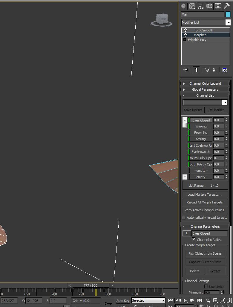
I found this section to be the most difficult part. Editing the UVW as an essential section of the UV mapping process as it allowed me to position selections of my face in areas where I wanted them to appear on the head. 

This process begins by applying an unwrap UVW modifier to the head. Using the cylindrical tool in map parameters I ensured that the map parameters covered the entire head. This ensured that nothing would be left out.

Mapping Parameters:


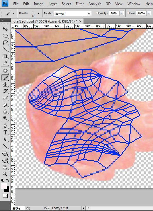
By selecting the head only, without the ear I could not enter the ‘edit’ mode under general parameters. In this mode I could now begin the process of stretching out the vertex points to enable the head to fit like a 2D image on the edit panel. By adding a checked material to the head allowed me to use the squares on the material to ensure that I was lining up the vertex points in the edit UVW panel correctly. By ensuring the squares on the checked material were as lined up as possible would ensure that the final UV map would fit onto my face correctly without any stretching or pinching of the skin. The badly tangled points could be tackled by selecting the vertex points and using either the ‘angles’ or ‘centre’ tool under the relax mode. This would automatically unwind some of the vertex points to a point so that it could then be done manually and easily.


Before editing the UVW vertex points:

After editing the UVW vertex points:


Now that the vertex points had been moved out into position, I could tell that they were in position because almost all of the squares were of square shape all over the face.  


In this next process I duplicated the side of the face in order to make a copy, to select a copy I used the ‘select element’ tool and ‘face-sub object mode’ . This copy was then mirrored (using the mirror tool) and placed into position so that it represented the other half of the head, the joining line being down the centre of the face.

Reverting back to the vertex mode, I now had to weld the join together so that the two sides of the head could now become 1 whole object. To do this I selected only the vertex points that were at the join and pressed ‘ctrl + W’ to weld.


Now that the head was welded and completed it was time to begin the process on the ears. This process was slightly different to the modelling of the head as it could be down quickly using the ‘relax’ tool.

By using the ‘point to point seam’ tool under map parameters I could select a split in the side of the ear so that when I placed it into the edit vertex mode the ear would split apart down the seam allowing me to spread the ear out more evenly, as detailed below:


Now by selecting the ear:


 By selecting the ear I
could edit the ear using the edit mode and use the same techniques as with the head to position the checked squares evenly. Once this process was completed I used the 'pelt tool' to place the ear into the edit UVW panel and be able to stretch the ear apart. I used the centre relax tool to even out the vertex points then duplicated the ear so and placed them in identical positions under the face.

To enable the face and both the ears to fit on the edit panel I had to change the size of the panel format to 512 x 256 pixels. This made the panel more of an oblong shape enabling me to fit the UVW mapping more easily.


Image of ear highlighted:


With both the head and the ear in position on the edit UVW panel I could now begin to export the image as a jpeg. This process was done by selecting the render option under tools. To render into the correct format ready for exporting the image to Photoshop it had to be a width of 4048 and a height of 1024 pixels. By selecting the render option the image UVW mapping would now be rendered as an image that would be saved as a jpeg using the save option.

This is what the final export of the UVW mapping should look like: