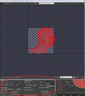
I found this section to be the most difficult part. Editing the UVW as an essential section of the UV mapping process as it allowed me to position selections of my face in areas where I wanted them to appear on the head.
This process begins by applying an unwrap UVW modifier to the head. Using the cylindrical tool in map parameters I ensured that the map parameters covered the entire head. This ensured that nothing would be left out.
Mapping Parameters:
By selecting the head only, without the ear I could not enter the ‘edit’ mode under general parameters. In this mode I could now begin the process of stretching out the vertex points to enable the head to fit like a 2D image on the edit panel. By adding a checked material to the head allowed me to use the squares on the material to ensure that I was lining up the vertex points in the edit UVW panel correctly. By ensuring the squares on the checked material were as lined up as possible would ensure that the final UV map would fit onto my face correctly without any stretching or pinching of the skin. The badly tangled points could be tackled by selecting the vertex points and using either the ‘angles’ or ‘centre’ tool under the relax mode. This would automatically unwind some of the vertex points to a point so that it could then be done manually and easily.
After editing the UVW vertex points:
Now that the vertex points had been moved out into position, I could tell that they were in position because almost all of the squares were of square shape all over the face.
In this next process I duplicated the side of the face in order to make a copy, to select a copy I used the ‘select element’ tool and ‘face-sub object mode’ . This copy was then mirrored (using the mirror tool) and placed into position so that it represented the other half of the head, the joining line being down the centre of the face.
Reverting back to the vertex mode, I now had to weld the join together so that the two sides of the head could now become 1 whole object. To do this I selected only the vertex points that were at the join and pressed ‘ctrl + W’ to weld.
Now that the head was welded and completed it was time to begin the process on the ears. This process was slightly different to the modelling of the head as it could be down quickly using the ‘relax’ tool.
By using the ‘point to point seam’ tool under map parameters I could select a split in the side of the ear so that when I placed it into the edit vertex mode the ear would split apart down the seam allowing me to spread the ear out more evenly, as detailed below:
Now by selecting the ear:
By selecting the ear I
could edit the ear using the edit mode and use the same techniques as with the head to position the checked squares evenly. Once this process was completed I used the 'pelt tool' to place the ear into the edit UVW panel and be able to stretch the ear apart. I used the centre relax tool to even out the vertex points then duplicated the ear so and placed them in identical positions under the face.
could edit the ear using the edit mode and use the same techniques as with the head to position the checked squares evenly. Once this process was completed I used the 'pelt tool' to place the ear into the edit UVW panel and be able to stretch the ear apart. I used the centre relax tool to even out the vertex points then duplicated the ear so and placed them in identical positions under the face.
To enable the face and both the ears to fit on the edit panel I had to change the size of the panel format to 512 x 256 pixels. This made the panel more of an oblong shape enabling me to fit the UVW mapping more easily.
With both the head and the ear in position on the edit UVW panel I could now begin to export the image as a jpeg. This process was done by selecting the render option under tools. To render into the correct format ready for exporting the image to Photoshop it had to be a width of 4048 and a height of 1024 pixels. By selecting the render option the image UVW mapping would now be rendered as an image that would be saved as a jpeg using the save option.
This is what the final export of the UVW mapping should look like:


No comments:
Post a Comment