This process begins with importing the exported Jpeg file that I created in 3DS Max and using it in Photoshop as a guide to align the materials to build the face.
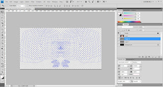
Once the jpeg file had been imported to Photoshop I created another layer and named it guide. This layer was created with a full blue filled background.
I then selected everything on the lower layer and created a layer mask. By selecting the lower layer and using the mask tool I could now extrude the lines that build the UVW mapping and turning them into a blue coloured guide by pasting them onto the blue filled layer. Adjustments were made using the modify border tool to increase the width of the newly created guidelines.
As detailed in the image below:
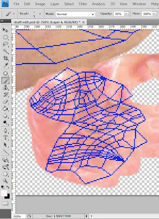
In this next process, I begun by opening the original image that I used to create the reference plane in 3DS Max. I removed the layer that contained the splines and begun cutting out sections of my face and transferring them over to a new layer underneath my newly created guide layer. The guide layer was extremely useful as it enabled me to position the sections of my face in the exact position so they would line up in 3DS Max on my face. I then saved a copy of the UVW mapping and uploaded it to 3DS Max and onto my face. This way every time that I saved the Photoshop file the newly saved contents would automatically be uploaded to 3DS Max and I could monitor my progress.
Cutting from the original:
Transferring to the UVW Mapping Guide:
Once I had finished the transferring of the facial sections it was now time to blend in all the edges of each of the sections. This process could be done with either the ‘stamp’ tool or the ‘patch’ tool.
These tools can be found on the right hand panel within Photoshop as detailed below:
I found the patch tool more useful in blending in the edges of each of the sections and the ‘stamp’ tool extremely useful to blend in sections of the hair and where the edge of the hair met the skin. It was vital I ensured that the colour tones across my face remained the same throughout as it had to look as realistic as possible to the original image.
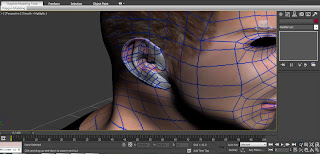
Once the blending of the face sections had been completed, I began the process of cutting out the sections of the ear and placing them in-line with the guidelines for the ear. I found this section extremely difficult as the ear had a complicated guideline structure from where I had used the pelt tool to flatten and stretch it out. Continuously saving the data file in Photoshop I could use 3DS Max as a guide to ensure that the sections of the ear were being placed in the correct sections.
This can be seen below:
I then used the same process to blend in the edges using the patch tool and I used the stamp tool to create extra shading within the deep areas of the ear to –re-create a more realistic look.
I found that the ear didn’t come out as detailed as expected and I felt that it didn’t really show a great deal when in 3DS Max on the ear. This I thought may have been to do with the resolution of the original image and the UVW mapping resolution save file. Attempts to alter the resolution were made but appeared to make no difference to the detailing in the ear.
The final UVW mapping image can be seen below:


No comments:
Post a Comment